funfasr
  • Blog
  • Home
  • Radio Code Calculator
  • Kmspico Windows 8 Pro Build 9600
  • Total Gym Elite
  • Major Crimes Season 6 Subtitles
  • Quilt Design Software
  • Streets Of Rage 2 Game Genie
  • Waldo Loli Pack 3 (19 Deposit Rar
  • Gino Sitson Torrent
  • Fha Approved Condos
  • Www Agenda Web. Org
  • How To Upload Photos On Gdca
  • Uru Ages Beyond Myst Download

Field Oriented Control

8/23/2019

 
Permanent magnet synchronous machine field-oriented control
  • Library:
  • Simscape / Electrical / Control / PMSM Control

Description

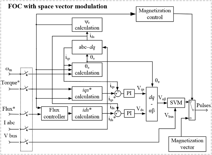
The PMSM Field-Oriented Control block implements a field-oriented control structure for a permanent magnet synchronous machine (PMSM). Field Oriented Control (FOC) is a performant AC motor control strategy that decouples torque and flux by transforming the stationary phase currents to a rotating frame. Use FOC when rotor speed and position are known and your application requires:
Slip: Field-oriented control or vector control is risky. It’s clearly more complicated and requires a higher level of motor control technical savvy than I do. It’s clearly more complicated and requires a higher level of motor control technical savvy than I do.
  • High torque and low current at startup.
  • High efficiency.

Equations

The PMSM FOC structure decouples the torque and flux by using the rotor d-q reference frame. This diagram shows the overall architecture of the block.
In the diagram:
  • ω and ωref are the measured and reference angular velocities, respectively.
  • Tref is the reference electromagnetic torque.
  • i and v are stator currents and voltages and subscripts d and q represent the d-axis and q-axis, and subscripts a, b, and c, represent the three stator windings.
  • θe is the rotor electrical angle.
  • G is a gate pulse, subscripts H and L, represent high and low, and subscripts a, b, and c represent the three stator windings.
You can choose to implement either velocity or torque control with the Control mode parameter. The block implements velocity control exactly as shown in the diagram. The block implements torque control by removing the Velocity Controller block and accepting the reference torque directly.

Limitations

The control structure is implemented with a single sample rate.

Input

System reference specified as torque reference in N*m or velocity reference in rad/s, depending on the control mode selected.
Data Types: single | double
Measured stator phase currents, in A.
Data Types: single | double
Measured mechanical angular velocity of rotor, in rad/s.
Data Types: single | double
Measured mechanical angle of rotor, in rad.
Data Types: single | double
Measured DC-link voltage, in V.
Data Types: single | double

Output

Six pulse waveforms that determine switching behavior in the attached power converter.
Data Types: single | double
Bus containing signals for visualization, including:
  • Reference
  • wElectrical
  • iabc
  • theta
  • Vdc
  • PwmEnable
  • TqRef
  • TqLim
  • idqRef
  • idq
  • vdqRef
  • modWave
Data Types: single | double

Parameters

General

Control Mode — Control mode strategy
Torque control (default) | Velocity control

Specify either a torque control or velocity control strategy.

Nominal dc-link voltage (V) — Rated DC voltage
300V (default) | positive number

Maximum power (W) — Maximum power
35000W (default) | positive number

Maximum torque (N*m) — Maximum torque
250N*m (default) | positive number

Number of rotor pole pairs — Pole pairs
8 (default) | positive integer

Number of permanent magnet pole pairs on the rotor.

Inverter dc-link voltage threshold (V) — DC-link voltage threshold
100V (default) | positive number

Fundamental sample time (s) — Block sample time
5e-6 (default) | positive number

Control sample time (s) — Control sample time
1e-4 (default) | positive number

Outer Loop

Control Type — Control type strategy
PI control (default) | P control | P-PI control

Controller proportional gain — Proportional gain of PI controller
1 (default) | positive number

Controller integral gain — Integral gain of PI controller
1 (default) | positive number

P controller proportional gain — Proportional gain of P controller
1 (default) | positive number

Integral anti-windup gain — Anti-windup gain
1 (default) | positive number

Current references — Current reference strategy
Zero d-axis control (default) | Lookup-table based | Automatically generated lookup-table

Mechanical speed vector, wMechanical (rpm) — Rotor speed lookup vector
[0, 3000]rpm (default) | positive monotonically increasing vector

Speed vector used in the lookup tables for determining current references.

Torque reference vector, TqRef (N*m) — Torque reference lookup vector
[-100, 0, 100]N*m (default) | positive monotonically increasing vector

Torque vector used in the lookup tables for determining current references.

DC-link voltage vector, Vdc (V) — DC-link voltage lookup vector
[300, 350]V (default) | positive monotonically increasing vector

: DC-link voltage vector used in the lookup tables for determining current references.

D-axis current reference matrix, id(wMechanical,TqRef,Vdc) (A) — Reference d-axis current values
zeros(2,3,2)A (default) | real matrix

Q-axis current reference matrix, iq(wMechanical,TqRef,Vdc) (A) — Reference q-axis current values
zeros(2,3,2)A (default) | real matrix

Permanent magnet flux linkage (Wb) — PM Flux Linkage
0.04Wb (default) | positive scalar

D-axis inductance (H) — Inductance of d-axis
0.00024 (default) | positive scalar

Q-axis inductance (H) — Inductance of q-axis
0.00029 (default) | positive scalar

Stator resistance (Ohm) — Resistance of stator
0.01 (default) | positive scalar

Inner Loop

D-axis current proportional gain — D-axis proportional gain
1 (default) | positive number

Proportional gain of the PI controller used for direct-axis current control.

D-axis current integral gain — D-axis integral gain
100 (default) | positive number

Integrator gain of the PI controller used for direct-axis current control.

D-axis current anti-windup gain — D-axis anti-windup gain
1 (default) | positive number

Anti-windup gain of the PI controller used for direct-axis current control.

Q-axis current proportional gain — Q-axis proportional gain
1 (default) | positive number

Proportional gain of the PI controller used for quadrature-axis current control.

Q-axis current integral gain — Q-axis integral gain
100 (default) | positive number

Integrator gain of the PI controller used for quadrature-axis current control.

Q-axis current anti-windup gain — Q-axis anti-windup gain
1 (default) | positive number

Anti-windup gain of the PI controller used for quadrature-axis current control.

Axis prioritization — Axis prioritization for voltage limiter
q-axis (default) | d-axis | d-q equivalence

Prioritize or maintain ratio between d- and q-axis when the block limits voltage.

Enable zero cancellation — Feedforward zero cancellation
off (default) | on

Enable or disable zero cancellation on the feedforward path.

Enable pre-control voltage — Precontrol voltage
on (default) | off

Machine parameters — Machine parameterization
Constant parameters (default) | Lookup table based parameters

Specify how to parameterize the machine.
  • Constant parameters — Specify machine parameters that are constant throughout the simulation.
  • Lookup table based parameters — Specify machine parameters as lookup tables that depend on current.

D-axis inductance for feed-forward pre-control (H) — Feedforward d-axis inductance
0.00024 (default) | positive scalar

Direct-axis inductance for feedforward precontrol.

Q-axis inductance for feedforward precontrol (H) — Feedforward q-axis inductance
0.00029 (default) | positive scalar

Quadrature-axis inductance for feed-forward pre-control.

Permanent magnet flux linkage for feedforward pre-control (H) — Feedforward flux linkage
0.04 (default) | scalar

Permanent magnet flux linkage for feedforward pre-control.

D-axis current vector, id (A) — D-axis current breakpoint vector
[-200,0,200]A (default) | monotonically increasing vector

Direct-axis current vector used in the lookup tables for parameters determination. For constant machine parameters, do not change the default.

Q-axis current vector, iq (A) — Q-axis current breakpoint vector
[-200,0,200]A (default) | monotonically increasing vector

Quadrature-axis current vector used in the lookup tables for parameters determination. For constant machine parameters, do not change the default.

Ld matrix, Ld(id,iq) (H) — D-axis inductance lookup data
0.0002 * ones(3, 3)H (default) | positive matrix

Ld matrix used as lookup table data. For constant machine parameters change only the constant factor, for example, Ld * ones(3, 3).

Lq matrix, Lq(id,iq) (H) — Q-axis inductance lookup data
0.0002 * ones(3, 3)H (default) | positive matrix

Lq matrix used as lookup table data. For constant machine parameters change only the constant factor, for example, Lq * ones(3, 3).

Permanent magnet flux linkage matrix, PM(id,iq) (Wb) — Flux linkage lookup data
0.04 * ones(3, 3)Wb (default) | real matrix

Permanent magnet flux linkage matrix used in the lookup table. For constant machine parameters change only the constant factor, for example, psim * ones(3, 3).
Field oriented control block diagram

PWM

PWM method — Pulse width modulation method
SVM: space vector modulation (default) | SPWM: sinusoidal PWM

Sampling mode — Wave-sampling method
Natural (default) | Asymmetric | Symmetric

Specify whether the block samples the modulation waveform when the waves intersect or when the carrier wave is at one or both of its boundary conditions.

Switching frequency (Hz) — Switching rate
1000 (default) | positive integer

Specify the rate at which you want the switches in the power converter to switch.

References

[1] Bernardes, T., V. F. Montagner, H. A. Gründling, and H. Pinheiro. 'Discrete-time sliding mode observer for sensorless vector control of permanent magnet synchronous machine.' IEEE Transactions on Industrial Electronics. Vol. 61, Number 4, 2014, pp. 1679–1691.
[2] Carpiuc, S., and C. Lazar. 'Fast real-time constrained predictive current control in permanent magnet synchronous machine-based automotive traction drives.' IEEE Transactions on Transportation Electrification. Vol.1, Number 4, 2015, pp. 326–335.
[3] Haque, M. E., L. Zhong, and M. F. Rahman. 'Improved trajectory control for an interior permanent magnet synchronous motor drive with extended operating limit.' Journal of Electrical & Electronics Engineering. Vol. 22, Number 1, 2003, p. 49.
[4] Yang, N., G. Luo, W. Liu, and K. Wang. 'Interior permanent magnet synchronous motor control for electric vehicle using look-up table.' In 7th International Power Electronics and Motion Control Conference. Vol. 2, 2012, pp. 1015–1019.

Extended Capabilities

C/C++ Code Generation
Generate C and C++ code using Simulink® Coder™.

See Also

Blocks

  • PMSM Current Controller | PMSM Current Controller with Pre-Control | PMSM Current Reference Generator

Topics

Introduced in R2017b


Comments are closed.

    Author

    Write something about yourself. No need to be fancy, just an overview.

    Archives

    August 2019

    Categories

    All

    RSS Feed

Powered by Create your own unique website with customizable templates.
  • Blog
  • Home
  • Radio Code Calculator
  • Kmspico Windows 8 Pro Build 9600
  • Total Gym Elite
  • Major Crimes Season 6 Subtitles
  • Quilt Design Software
  • Streets Of Rage 2 Game Genie
  • Waldo Loli Pack 3 (19 Deposit Rar
  • Gino Sitson Torrent
  • Fha Approved Condos
  • Www Agenda Web. Org
  • How To Upload Photos On Gdca
  • Uru Ages Beyond Myst Download